Before you get started, you can upload Eagle .brd files directly and we’ll generate the gerbers for you. For most users, this is the best way to order a board designed with Eagle.
Generating Drill Files. To create a Gerber file in Eagle, you should run the drillcfg command first: File -Run ULP - the pop-up 'Drill Configuration' dialog box and click the 'OK' button to generate the corresponding drill configuration file. Open the.brd file, and then click the 'File' menu to open the 'CAM Processor' dialog box. PCB design software for everyone Included with a Fusion 360 for personal use subscription, EAGLE free download is a limited version for hobbyists including 2 schematic sheets, 2 signal layers, and an 80cm2 (12.4in2) board area. Eagle Schematic/PCB/libs can be imported, but EasyEDA can only support version 6 and later (6+) because that was when Version 6 Eagle adopted an ASCII XML data structure as their native file format. If your Eagle file can be open in Eagle, but can’t be imported in EasyEDA, you can save as a copy with the latest Eagle, and then import it. First of all, you will need to open your PCB design file in Eagle. This file will have a.brd extension. After that, following the following instructions: 1.Select “File - CAM Processor”. Download Managers Web Browsers Messaging Software Antivirus Software Video Players Image Editing Software Video Editing Software File Compression Software PDF Readers Audio Players GIS Software Webcam Software Screencasting Software DJ Software Browser Plug-ins Video Converters 2D Animation Software Gaming Clients File Managers BitTorrent.
Sometimes though, you might want to customize the silkscreen, manually verify the gerber files, or other things that require manufacturing files. This guide will help with that.
Pcb File Open
We provide a standard CAM file that will automatically configure Eagle to a good starting point.
First Steps
Validate Board Outline
One of the most common errors we see for Eagle is a missing Board Outline. Verifying your outline will save you a lot of trouble.

Eagle expects this to be drawn on the Dimension layer, using the Wire or Line tools. For many designs, it’s a simple rectangle or circle that contains your design. We’ll cut your PCB out using this layer as a guide.
Download CAM files
We have published some scripts to automatically download, install, and update our files for Eagle. This is our recommended way to manage your CAM jobs.
Downloading Manually (Manual)
Select the correct CAM file for your version of Eagle, and how many layers you want to use.
For Eagle 7.2 and newer:
For Eagle 7.1, Eagle 6, and Eagle 5:
A good place to save this is in your Eagle folder in the cam/ directory, since Eagle will assume your CAM files are in this folder.
Configuring CAM Output
Load CAM file
To load the downloaded CAM file, open your board layout window. Then, open the CAM processor by going to File > CAM Processor
In the new window, select File > Open Job, browse to the downloaded file, and select open.
Modify Layer Configuration (Optional)
Once the CAM file is loaded, you may optionally adjust the CAM files to suit your design. The most common adjustment is to add or remove layers that will be included on the silkscreen.
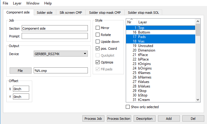
The tabs on top each represent a single Gerber file and a single layer on a fabricated PCB. The list on the right indicates the Eagle layers will be included in this file. It’s common for multiple Eagle layers to be used to generate a single Gerber file.
To adjust the layers used in each file, select the tab (such asTop Silkscreen), and check or uncheck any layers you would like printed. For a full list of layers and what they typically do, see our Eagle Layers Explained page.
As an example, you can include component values by selecting tValues, turn off component names by de-selecting tNames, or show all the Top traces on the top silkscreen by selecting Top.
Note, that while you can configure arbitrary Eagle layers to be included in arbitrary Gerber files, doing so impact the functionality of the board. Silkscreen files are purely cosmetic and safe to change, but excercise caution and verify your gerbers whenever you adjust any other gerber file layer configuration.
Generate the Files
Once the CAM file is loaded and configured to your liking, simply click Process Job. Eagle will then generate the .ger and .xln files in the same folder as your .brd file.
Eagle will also generate several .gpi and .dri files, which can be deleted or ignore.
From here simply zip the output files, and upload it to oshpark.com
Gerber files are kind of a “universal language” for PCB designs. Most manufacturers accept it. So when you finish your design, you need to generate a Gerber file. Maybe your file is (BRD) or (SCH), and so on, then you need to convert the file to a Gerber file.
This article will teach you step-by-step on how to use the eagle to generate or convert Gerber files and excel files
Pcb File Types
Choosing a reliable manufacturer is a important thing when you after your design, there are some factors you need take into consideration:
1.Can help you quickly check if there any problems in your design?
2.Can they meet any special requirements in your design?
3.Lead-Time, Quality, and then the Price is acceptable.
1.Gerber Files
Before we start next step, you’ll need to download another definition file:CAM file.
EAGLE provides a CAM job file, which will create your GERBER files for a, 2 layer board in an easy fashion. Please follow these steps:
First, download these files:
1.Load your board on the screen.
To do this from the EAGLE Control Panel, click on File/Open/Board and select the board you will use.
2.Click on the Icon on the top Tool bar that says ULP.
When the dialog box appears select the ULP file called DRILLCFG.ULP from the ULP directory. In a matter of seconds the command line you will notice a message saying ULP has finished.
3.Now click on the Icon that stands for the CAM Processor.
This will load the CAM Processor Screen. From this screen click on File/Open/Job (when asked to save “Modified Job” reply NO) and select the CAM job called GERBER.CAM from the CAM directory and click OK.
4.Now, click on the button that says Process Job.
This will prompt you with 2 messages. The first message will be “Delete the $$$ file after process” this is a dummy file that EAGLE creates; click OK. The second message is “More than one signal layer Active,” Click OK to this message as well. Depending on the board’s size and complexity, the entire process will take a few minutes or a few hours.
5.When the CAM Processor stops all process it means it has finished.

This process created several files that will have the same name as your board with different extensions:
.WHL Aperture Wheel File .PLC Silk Screen Component side
.CMP Copper Component side .STC Solder Stop mask Component side
.SOL Copper Solder side .STS Solder Stop mask Solder side
Then you need to zip the following files and deliver it to PCB Manufacturer
*The GTP file isn’t necessary for the PCB fabrication, because it is used to create a stencil(if your design had SMD parts) .
2.Excellon Files
(Make sure you have done step 1 and 2 before proceeding with Excellon files)
• Directly from the CAM processor click on File/Open/Job and select the CAM Job called EXCELLON.CAM from the CAM directory, then click OK.

• Now click on the small button that says Process. This will begin the EXCELLON file generation. Normally this process only takes a few seconds.
• The following files are created when the process ends.
.DRL Tool Rack File .DRD Excellon. Output.DRI Drill Information file
ICONS

CAM Processor User Language Program (ULP)
Adding Layers to the existing GERBER.CAM file
(Refer to your EAGLE 3.55 manual page 86.
The first page of this document teaches you how to create all the necessary Gerber files for a 2 sided board. But due to the growing demand for more than 2 layers we decided to add this portion to this document.
Initially GERBER.CAM generates all of the apertures needed to make a 2 sided board. By modifying the GERBER.CAM process we can easily add more steps to the CAM processor to take care of our additional layers.
Lets begin:
1.From the EAGLE control panel click on File/Open/Board and select the board you are interested in.
2.Click on the CAM processor ICON.
3.Now click File/Open/JOB and select the file called GERBER.
CAM from the CAM directory. If EAGLE prompts you to save the current process. Click NO.
4.Notice on the CAM processor screen a field called SECTION.
If, the section called “Generate a wheel file” is not visible, then click on the down arrow at the end of the section and select the section called Generate a Wheel File.
5.On the right hand side of the CAM processor screen you will notice the layer list.
Tag the additional layers you wish to include: Any inner layers or maybe the bottom silk screen layers (BPlace and BName). DO NOT UNTAG ANY OF THE OTHER LAYERS. Click on File/Save Job to save what we have done so far. I would recommend giving this CAM job a different name. For example, 4Layer.cam)
Open Pcb File Online
6.After tagging all the necessary layers click on the SECTION down arrow and select the very last section called Solder Stop Mask SOL.
7.Click on the ADD button. EAGLE will ask you to name the new section you are creating. You can give it any name you feel comfortable with, example, call it INNER POWER PLANE VCC, INNER SIGNAL LAYER 2, or BOTTOM SILK SCREEN). Click OK when done.
Eagle Pcb Download

8.Now select the appropriate layer for this section. The inner power plane (for example $GND) only selects that layer by itself. Bottom silkscreen layer tag the Dimension, place, and BName layers. If it’s a regular signal layer combine it with PAD’s and VIA’s MAKE SURE NO OTHER LAYERS ARE TAGGED.
9.Change the name of the output. Use the table in the bottom of this page as an example.
10.Create a new section for every new layer needed. Repeat step 7, 8, 9 and 10 for every new layer.
Go to step 4 on page number 1.